
Energy on Board: How to Combine Batteries, an Inverter and Solar Panels
A practical guide to how a Victron Energy system supplies everyday onboard needs, from refrigeration and lighting to laptop charging.
A refrigerator runs between meals, navigation instruments work while you are underway, and a kettle needs considerable power for only a few minutes. A useful onboard energy system must handle both how much power equipment needs at once and how much energy it uses over time.
This guide explains a system with solar charging on the DC side, using official Victron Energy documents. PLC Marine’s diagrams and worked examples illustrate those principles; the assumed loads and percentages are not Victron product ratings or a ready-to-install equipment package.
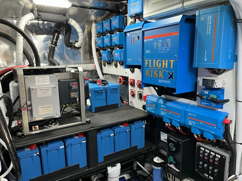
The Victron products behind the system
Official Victron product photographs show the role of each component. The models pictured are examples from the range; voltage and equipment selection must be checked for each boat.
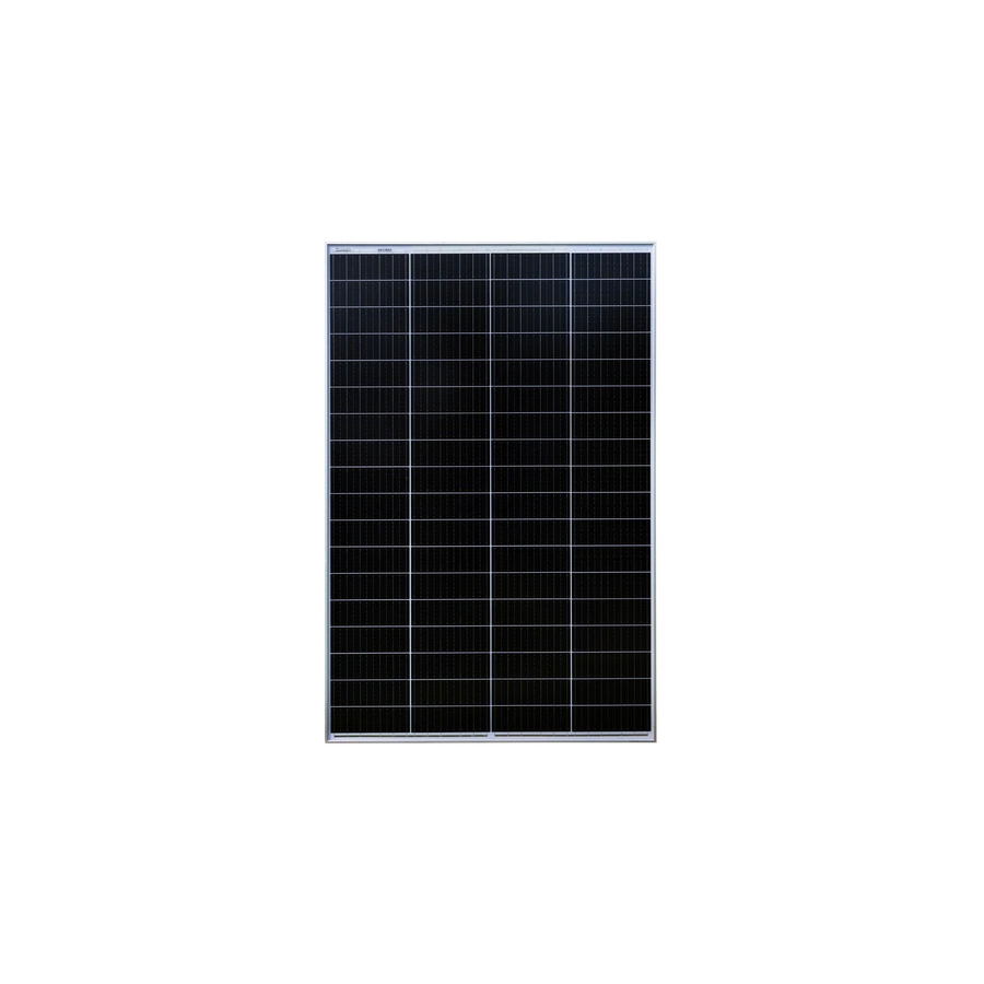
BlueSolar 235 W
Generates DC electricity from sunlight. Match the solar array’s voltage and current to the selected MPPT controller.
View at Victron Energy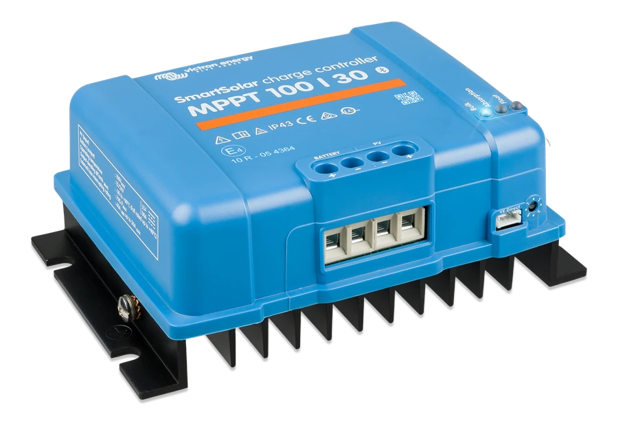
SmartSolar MPPT 100/30
Regulates the energy from the panels to charge the battery. Configure the charging profile for the battery in use.
View at Victron Energy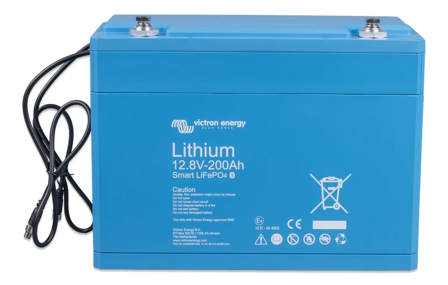
Lithium Battery Smart 12.8 V / 200 Ah
Stores energy for the onboard DC system. This Victron battery range requires a compatible external BMS.
View at Victron Energy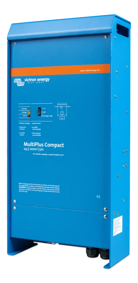
MultiPlus Compact 24/2000
Combines an inverter, battery charger and AC transfer function. The photographed version uses a 24 V battery system and provides 120 V AC; the worked example below uses a different, 12 V model.
View at Victron Energy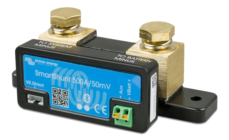
SmartShunt 500 A
Measures battery current and helps track state of charge through VictronConnect.
View at Victron Energy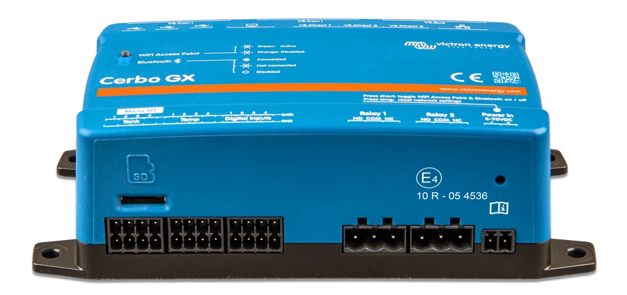
Cerbo GX MK2
Brings information from compatible Victron equipment together. Remote monitoring through VRM requires an internet connection.
View at Victron EnergyWhat each component does
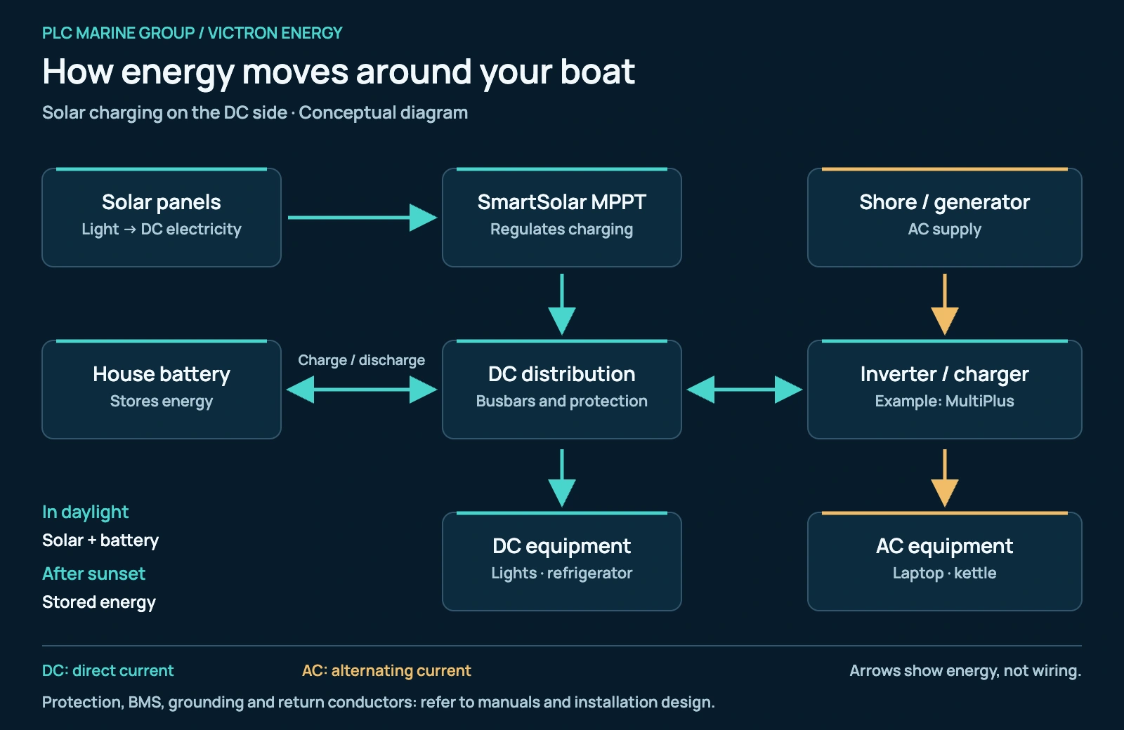
Solar panels generate DC electricity. A SmartSolar MPPT controller adjusts the panels’ operating point and regulates battery charging. The charging settings must suit the battery. The controller is a charger, not an AC inverter. Victron SmartSolar.
The house battery stores energy. It can supply suitably matched DC equipment, such as lighting and refrigeration, through the vessel’s protected DC distribution. The MPPT, battery and inverter share this DC system; solar energy can support operating loads as well as recharge the battery. Victron MPPT connection diagram.
An inverter converts DC into AC for compatible AC appliances. An inverter/charger, such as MultiPlus, also charges the battery from an accepted shore or generator AC supply and incorporates a transfer function. AC appliances connect to the appropriate AC distribution; they do not connect directly to a solar panel. Victron MultiPlus.
At anchor, after sunset and at the dock
- Daytime at anchor: Solar contributes to the DC system. When available charging power exceeds demand and the battery can accept it, the surplus charges the battery. If demand is greater, the battery supplies the shortfall.
- After sunset: Solar generation stops. The battery supplies the DC loads and the inverter’s DC input for any AC appliances being used.
- Connected to shore power: A MultiPlus can supply its connected AC loads from the accepted AC input and charge the battery. PowerControl reduces battery charging to respect the configured AC input-current limit; PowerAssist can use battery energy to help with short periods of higher demand, within the system’s limits.
These operating paths follow the Victron MPPT connection layout and MultiPlus operating description. Solar can reduce reliance on shore power, but rigging shadows and available panel space affect what is possible on a boat. Victron marine systems.
A worked example: one day’s onboard needs
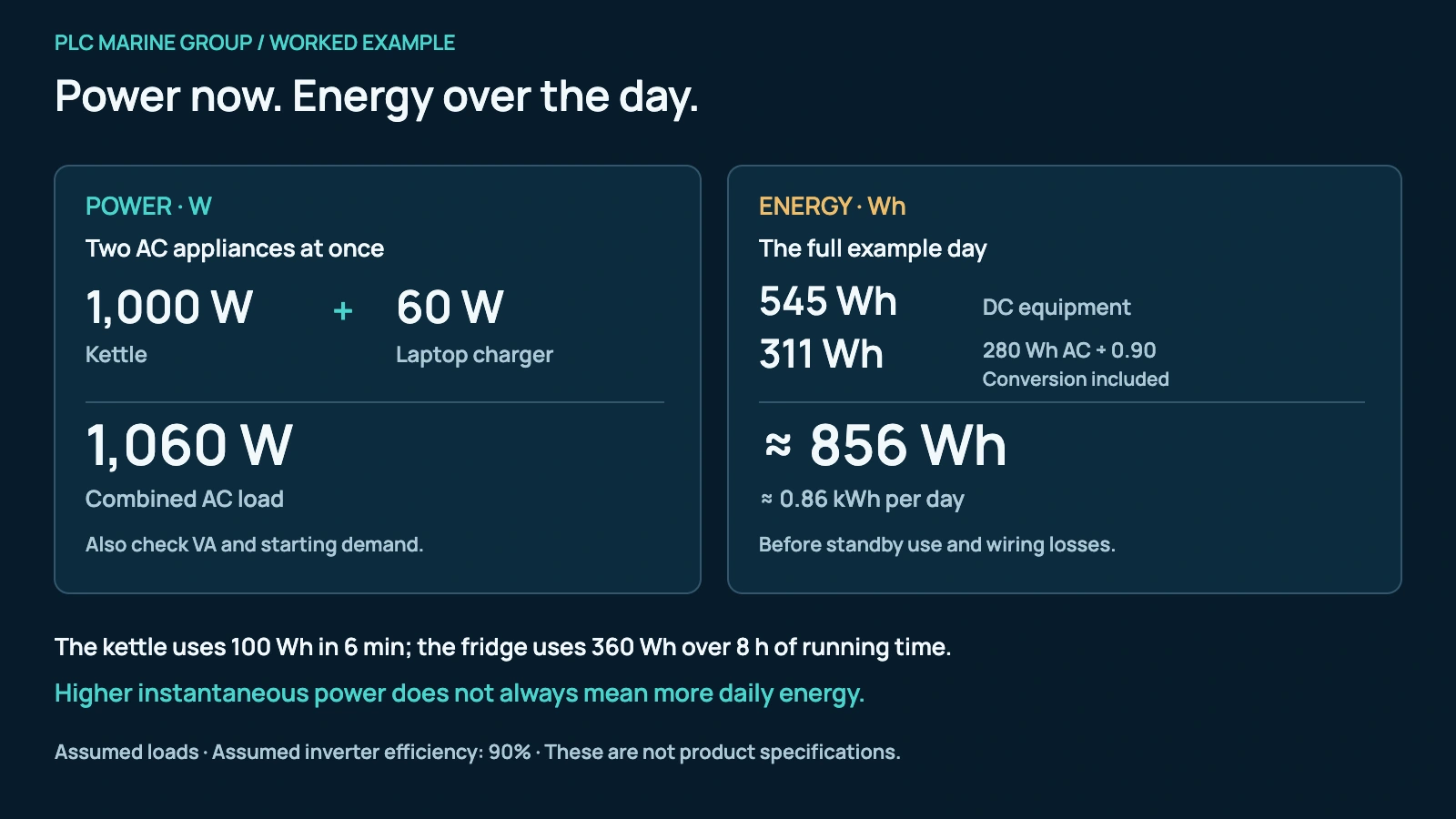
Energy (Wh) = power (W) × operating time (h). Watts describe the instantaneous load; watt-hours describe the energy used. Start with an equipment list, then measure or verify consumption for the actual boat. Victron’s Energy Unlimited uses this approach for onboard equipment, including refrigeration that cycles on and off.
The following figures are assumptions for a teaching example, not typical consumption guaranteed for any appliance. The refrigerator’s eight hours mean accumulated compressor running time within a 24-hour day.
| Equipment / supply | Assumed power | Running time per day | Energy |
|---|---|---|---|
| Refrigerator · DC | 45 W | 8 h | 360 Wh |
| Navigation instruments · DC | 20 W | 6 h | 120 Wh |
| LED lighting · DC | 10 W | 5 h | 50 Wh |
| Freshwater pump · DC | 60 W | 0.25 h / 15 min | 15 Wh |
| Laptop charger · AC | 60 W | 3 h | 180 Wh |
| Kettle · AC | 1,000 W | 0.10 h / 6 min | 100 Wh |
Refrigerator · DC
- Assumed power
- 45 W
- Running time per day
- 8 h
- Energy
- 360 Wh
Navigation instruments · DC
- Assumed power
- 20 W
- Running time per day
- 6 h
- Energy
- 120 Wh
LED lighting · DC
- Assumed power
- 10 W
- Running time per day
- 5 h
- Energy
- 50 Wh
Freshwater pump · DC
- Assumed power
- 60 W
- Running time per day
- 0.25 h / 15 min
- Energy
- 15 Wh
Laptop charger · AC
- Assumed power
- 60 W
- Running time per day
- 3 h
- Energy
- 180 Wh
Kettle · AC
- Assumed power
- 1,000 W
- Running time per day
- 0.10 h / 6 min
- Energy
- 100 Wh
DC subtotal: 545 Wh. AC subtotal: 280 Wh. These are example inputs, not product specifications.
Allow for conversion losses. At an assumed 90% inverter efficiency under load, the AC appliances require 280 ÷ 0.90 ≈ 311 Wh from the DC system. The combined demand is therefore 545 + 311 ≈ 856 Wh, or 0.86 kWh per day, before additional standby consumption and wiring losses.
The kettle has the highest power requirement but uses less daily energy than the refrigerator in this example. Add any autopilot, communications, pumps, entertainment, air conditioning or other equipment actually used; none is included in this total.
Battery capacity: distinguish nominal energy from usable energy
For an illustrative 12.8 V, 200 Ah battery bank, nominal energy is 12.8 × 200 = 2,560 Wh. If the operating plan allows 80% of that nominal energy to be used, the working allowance is 2,048 Wh. The 80% figure is an assumption for this example, not a universal discharge limit.
Choose the usable fraction and reserve for the actual battery chemistry, manufacturer limits and required time without charging. Temperature, discharge rate and battery condition affect available capacity; the illustrative daily total above also omits some losses. A nominal capacity alone does not establish real autonomy. Victron on battery behaviour; Victron energy planning.
Inverter selection: check watts, starting demand and voltage
Add the AC loads that may run together and check their starting demand. VA and W are different ratings: the inverter must meet both the apparent-power and real-power requirements. Victron explanation of VA and watts. Match its DC voltage to the battery system and its AC voltage and frequency to the boat’s equipment.
One concrete example: Victron’s MultiPlus 12/2000/80-50, 120 V data sheet lists 2,000 VA and 1,600 W continuous at 25°C, falling to 1,400 W at 40°C. “2000” in that model name does not mean 2,000 W continuous. These figures apply to that specified model, not every MultiPlus. Official 120 V data sheet.
The battery side matters too. A 1,000 W AC load at an assumed 90% efficiency and 12.8 V requires approximately 1,000 ÷ (0.90 × 12.8) = 87 A, before additional losses. Battery/BMS current capability, cable size and protection must support the intended load and any starting surge. Victron DC power and current principles.
Solar: plan daily recovery, then check the controller
Panel watts are not a daily energy figure. For an illustrative 400 W array, 4 peak sun hours and an assumed 75% overall solar-path yield factor, the planning result is 400 × 4 × 0.75 = 1,200 Wh/day at the DC system. Peak sun hours represent equivalent full-sun energy, not the total hours of daylight. The four hours and 75% are example assumptions, not a forecast for Mexico or a SmartSolar efficiency specification. Victron’s solar-sizing method.
Check the actual location, season, shading, panel orientation and installation losses. An MPPT helps extract available panel power; it does not remove the loss caused by shade. Plan how to recover from low-solar days and allow for battery charging losses. Victron’s marine solar considerations; battery charge efficiency.
For the SmartSolar MPPT 100/30, “100” denotes the maximum PV open-circuit voltage and “30” the rated battery charge current in amperes. Victron lists 440 W nominal PV power at 12 V, but wattage alone does not confirm a panel combination: check cold-weather Voc, PV short-circuit current, charging current and the minimum operating voltage against the exact manual. Official MPPT specifications; array installation checks.
Two decisions that must work together
A bigger battery does not increase the inverter’s AC rating. A bigger inverter does not add stored energy. More solar helps recharge the system when sunlight is available, while the battery and inverter must still cover the loads that occur at night or exceed current solar production.
Measure energy use and keep battery protection separate
A SmartShunt measures battery current and helps calculate state of charge. To account for all charging and discharging, the relevant system returns must be on the system side of the shunt. Correct battery settings and synchronisation are essential to useful readings. SmartShunt installation; configuration.
Monitoring does not replace battery protection. Victron’s Lithium Battery Smart range requires a compatible external BMS; built-in cell balancing is not a substitute for that requirement. Check the BMS specified for the exact battery range. Lithium Battery Smart requirements.
A Cerbo GX can bring compatible system information together. Remote access through VRM needs the appropriate connections and internet access; it is distinct from local device access. Cerbo GX; MultiPlus monitoring requirements.
Turn the example into a system for your boat
Before choosing equipment, record the boat’s DC and AC voltages, appliance ratings, simultaneous loads, daily operating hours, battery chemistry, existing charging sources and unshaded panel space. The installation must also account for DC fuses, isolation, cable voltage drop and AC electrical protection. Victron’s Wiring Unlimited explains why these are part of the system design.
Have a qualified marine electrical installer check the complete design and the manuals for the selected equipment. The diagrams explain operation; they do not specify cable sizes, fuse values or grounding arrangements.
Contact PLC Marine with your equipment list and current installation details to discuss a Victron Energy system suited to your onboard needs.
Official Victron sources
Technical explanations were checked against Victron’s own product pages, manuals and technical publications. The solar-sizing article is written for RVs; only its energy-accounting method is used here, with marine installation considerations taken from Victron’s marine material and equipment manuals.